|
|
|
Porsche, and the Porsche crest are registered trademarks of Dr. Ing. h.c. F. Porsche AG.
This site is not affiliated with Porsche in any way. Its only purpose is to provide an online forum for car enthusiasts. All other trademarks are property of their respective owners. |
|
|

  |

| 914werke |
 Mar 16 2023, 05:25 PM Mar 16 2023, 05:25 PM
Post
#1
|
|
"I got blisters on me fingers"  Group: Members Posts: 11,248 Joined: 22-March 03 From: USofA Member No.: 453 Region Association: Pacific Northwest |
So seeing a product recently got me thinking about the result of its application & my own observations of how well (or not) the T4 handles air flow, Engine block cooling & resulting oil temperatures. (IMG:style_emoticons/default/smile.gif)
Its somewhat well known that ...in the 914.. the T4 suffers from less than optimal cooling from the front mounted impeller/fan particularly to the #3 Cylinder & that it is vitally important to seal the tins multiple openings to contain as much laminar air flow front to back over the finned cylinders. In a gross approach, the goal was to seal the engine compartment "intake" air on top from the eng. heated "cooling" air below the tins. When a motor is new and all its components serviced & refreshed, the design does, or did, a pretty good job. After years of use (neglect), elements (oil dirt mice ext) conspire to restrict that air flow. As well as eng. heat causing hardening of rubber pieces that are intended to help contain that cooling air below. Now almost 50 yrs on I see fewer & fewer "STOCK" engine configurations which you can guess usually means more heat to deal with. Jake addressed the cooling air via his(?) DTM solution, but IMO its not very practical for stock or near stock motors (& expensive) The go-to response to eliminate that heat is usually an additional or a remote oil cooler which comes with its own set of challenges. (IMG:style_emoticons/default/confused24.gif) How about KISS (IMG:style_emoticons/default/biggrin.gif) Has anyone used any of the Fiberglass based stick-on reflective heat shielding products on the engine-sides of the tin? Idea being rather than allow heat absorption to all the those steel pieces reflect it back to carried away by the cooling air? BTW Im not a Porsche engineer...but I did stay in a Holiday Inn last night (IMG:style_emoticons/default/happy11.gif) |
   |

 
|
| technicalninja |
Mar 16 2023, 06:03 PM
Post
#2
|
|
Advanced Member Group: Members Posts: 2,531 Joined: 31-January 23 From: Granbury Texas Member No.: 27,135 Region Association: Southwest Region |
That's possible a good idea...
Done right it might help with air leaks as well. I've used DEI sticky back sheets on firewalls and evaporator cases many times and it does kick ass on stopping heat transfer. I'm very interested in what you find/try. please post results. It would be very helpful to change the area above the engine lid to a high-pressure area instead of the low-pressure area that currently exists. That would help better than the plastic flaps on the bottom do... |
|
|
|
| mepstein |
Mar 16 2023, 07:07 PM
Post
#3
|
|
914-6 GT in waiting Group: Members Posts: 19,876 Joined: 19-September 09 From: Landenberg, PA/Wilmington, DE Member No.: 10,825 Region Association: MidAtlantic Region |
An oil cooler with a fan pack seems like the way to go. Proven to work, even when the cars not moving. Just look at 911’s for the engine cooling evolution. Fans hardly got bigger. Tin and layout stayed mostly the same. The big difference was increased oil cooling. I’m sure there are alternatives for dropping a couple degrees but I can’t think of another - works every time on any air cooled engine - than cooling the oil.
|
|
|
|
| Lockwodo |
Mar 16 2023, 07:37 PM
Post
#4
|
|
Member Group: Members Posts: 214 Joined: 23-December 21 From: Santa Cruz, Californnia Member No.: 26,193 Region Association: Northern California |
QUOTE(914werke @ Mar 16 2023, 04:25 PM)  So seeing a product recently got me thinking about the result of its application & my own observations of how well (or not) the T4 handles air flow, Engine block cooling & resulting oil temperatures. (IMG:style_emoticons/default/smile.gif) Its somewhat well known that ...in the 914.. the T4 suffers from less than optimal cooling from the front mounted impeller/fan particularly to the #3 Cylinder & that it is vitally important to seal the tins multiple openings to contain as much laminar air flow front to back over the finned cylinders. In a gross approach, the goal was to seal the engine compartment "intake" air on top from the eng. heated "cooling" air below the tins. When a motor is new and all its components serviced & refreshed, the design does, or did, a pretty good job. After years of use (neglect), elements (oil dirt mice ext) conspire to restrict that air flow. As well as eng. heat causing hardening of rubber pieces that are intended to help contain that cooling air below. Now almost 50 yrs on I see fewer & fewer "STOCK" engine configurations which you can guess usually means more heat to deal with. Jake addressed the cooling air via his(?) DTM solution, but IMO its not very practical for stock or near stock motors (& expensive) The go-to response to eliminate that heat is usually an additional or a remote oil cooler which comes with its own set of challenges. (IMG:style_emoticons/default/confused24.gif) How about KISS (IMG:style_emoticons/default/biggrin.gif) Has anyone used any of the Fiberglass based stick-on reflective heat shielding products on the engine-sides of the tin? Idea being rather than allow heat absorption to all the those steel pieces reflect it back to carried away by the cooling air? BTW Im not a Porsche engineer...but I did stay in a Holiday Inn last night (IMG:style_emoticons/default/happy11.gif) Wondering how to tell how well the tins are sealed? Is there a smoke test that can be used? With the engine idling, if I remove one of the tin seals (for example, the grommet over the CHT) what should the velocity of the escaping air be? |
|
|
|
| 914werke |
Mar 16 2023, 07:43 PM
Post
#5
|
|
"I got blisters on me fingers" Group: Members Posts: 11,248 Joined: 22-March 03 From: USofA Member No.: 453 Region Association: Pacific Northwest |
Not debating that adding oil cooling does the job. It is tried & true, but comparing a /4s oiling circuit to a /6's is apples & oranges.
Ive seen a # of /4's with additional oil cooling setups ... that are completely unnecessary. Often preventing engine temps coming up to allow the motor to perform optimally Not everyone lives in Texas or Arizona |
|
|
|
| technicalninja |
Mar 16 2023, 07:52 PM
Post
#6
|
|
Advanced Member Group: Members Posts: 2,531 Joined: 31-January 23 From: Granbury Texas Member No.: 27,135 Region Association: Southwest Region |
QUOTE(914werke @ Mar 16 2023, 08:43 PM) Not debating that adding oil cooling does the job. It is tried & true, but comparing a /4s oiling circuit to a /6's is apples & oranges. Ive seen a # of /4's with additional oil cooling setups ... that are completely unnecessary. Often preventing engine temps coming up to allow the motor to perform optimally Not everyone lives in Texas or Arizona Some of us freakin do... It can be hotter than hell here. That's one of the reasons I have an automotive ac shop. People will pay GOLD for cool air when it's 100+... I'm going to do anything and everything to improve cooling my air-cooled wonder. That's why I'm interested in your idea. Hadn't thought about it before you mentioned it but... You're right! |
|
|
|
| 914werke |
Mar 16 2023, 10:15 PM
Post
#7
|
|
"I got blisters on me fingers" Group: Members Posts: 11,248 Joined: 22-March 03 From: USofA Member No.: 453 Region Association: Pacific Northwest |
QUOTE(Lockwodo @ Mar 16 2023, 06:37 PM) Wondering how to tell how well the tins are sealed? Is there a smoke test that can be used? With the engine idling, if I remove one of the tin seals (for example, the grommet over the CHT) what should the velocity of the escaping air be? Interesting question. (IMG:style_emoticons/default/idea.gif) Ive never used smoke to validate the cooling tin sealing. I dont know what kind of "pressure" to expect in such a sceaniro. That test would be feeding smoke into the impeller opening while stationairy so you may also need a fan blowing air under the car from the front to recognize the low pressure tumble effect of the flaps at the bottom of the car. |
|
|
|
| Superhawk996 |
Mar 16 2023, 11:13 PM
Post
#8
|
|
914 Guru Group: Members Posts: 7,038 Joined: 25-August 18 From: Woods of N. Idaho Member No.: 22,428 Region Association: Galt's Gulch |
Bottom line: reflective heat shield on the interior of the tin isn’t going to amount to any noticeable cooling improvement.
Why not? There are three modes of heat transfer taking place in cooling an engine. Convection (this is the dominant one via the fan) Conduction Radiation Let’s talk about radiation 1st. Radiation emitted from an object (the engine) is not affected by what surrounds it regardless of whether it is surrounded by air, steel tin (914) or a fiberglass shroud (911). Radiation emitted from the object is determined by the temperature of the object to the fourth power. I.e temperature of the object is the dominant factor. Radiant energy travels though a vacuum. Radiant energy travels though gasses (air) with minimal loss of energy. Radiant heat energy isn’t effectively cooled until it is absorbed into another object, at which point that object is cooled by either convection or conduction. Even if you were able to prevent the radiant heat energy that is emitted from the engine from being absorbed into the tin completely, you would still have heat conduction into the tin since the tin is attached to the heads and the case. So you might ask . . . why not insulate the tin from the engine to reduce the thermal conduction? Let’s consider 911 cooling shrouds that are fiberglass. We could also consider the new carbon fiber T4 “tin” that Type 4 Store is now offering for the 914. In either example, the conduction from the engine to the “tin” is greatly reduced because fiberglass and carbon fiber are not as thermally conductive as steel. Would you agree that neither of these (better insulated) shroud configurations or materials make a huge difference to the overall cooling? Finally, don’t forget that the inside surface area of the tin (or 911 shroud) is also being cooled by forced air convection. By placing what will effectively be insulation layer inside of the tin, you’re losing the contribution of convective cooling of the tin that has absorbed that heat radiation the engine produced. Some heat is being conducted out of the engine into the tin by conduction, and then the inside surface area of the tin is then convectively cooled by the fan (on the inside) and ambient engine bay air on the outside of the tin. Do you want to lose this convection cooling effect that the tin provides even if it is very minimal? Sorry for the long answer. |
|
|
|
| Superhawk996 |
Mar 17 2023, 11:06 AM
Post
#9
|
|
914 Guru Group: Members Posts: 7,038 Joined: 25-August 18 From: Woods of N. Idaho Member No.: 22,428 Region Association: Galt's Gulch |
I was thinking about this a little more.
What might be interesting is to have the “tin” made of aluminum. Aluminum conducts heat better than steel. Why not use that to help draw heat out of the case and the heads a little more quickly. Making use of the enhanced conduction to get the heat into the aluminum shroud. Then it can be carried away by the forced convection provided by the fan. Taking this a step further, could some fins be placed in strategic areas inside the tin to add even more surface area to the shroud so that the convection is more efficient? Fins would have to be parallel with the air flow to minimize flow restriction. (IMG:style_emoticons/default/idea.gif) Copper is even more thermally conductive than aluminum. Pricy but amazing at thermal conduction 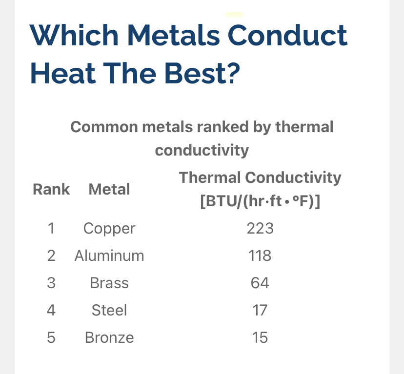 Would sort of look cool all polished up on outside. Might be time to think of extending the copper metal shaping to a set of 914 “tin”. 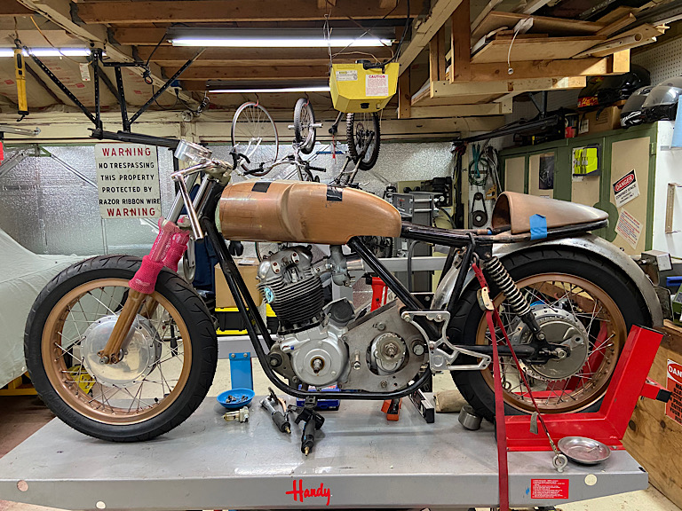 I think I should at least finish the Norton before I get that distracted. (IMG:style_emoticons/default/laugh.gif) |
|
|
|
| Superhawk996 |
Mar 17 2023, 11:38 AM
Post
#10
|
|
914 Guru Group: Members Posts: 7,038 Joined: 25-August 18 From: Woods of N. Idaho Member No.: 22,428 Region Association: Galt's Gulch |
Still thinking about this. Not sure copper “tin” would net much improvement.
Why not? The convective cooling of the engine by air is a function of the temperature delta between the air and the cylinder heads. If the cooling air effectively gets pre-heated by picking up lots of heat from the tin, then the air is less effective at cooling the head. In this case, I’m not sure how much of a temperature rise would occur if the “tin” was really effective? Would be interesting to do some CFD thermal modeling to understand it better before making parts. Would also be interesting to set up a bunch of thermocouples to measure it if parts were made. About a year or two ago I did work up some napkin sketch assumptions showing that getting cooler ambient air into the engine compartment didn’t make as much of a cooling improvement as some thought it ought to. This is because the temperature delta is dominated by the head temperature which is 2-3 times hotter than ambient air. Example delta Temp = head temp - ambient air. So we end up with something like 300F (head) - 100F ambient air = delta T of 200F So let’s ASSUME that the copper tin allows the cooling air to preheat by 20F more than steel. Now we have 300F - 120F = 180 delta T for the air available to cool the head. 10% less delta Temp available to cool the head. See why this might not actually net improved cooling? |
|
|
|
| GregAmy |
Mar 17 2023, 12:40 PM
Post
#11
|
|
Advanced Member Group: Members Posts: 2,490 Joined: 22-February 13 From: Middletown CT Member No.: 15,565 Region Association: North East States |
Coming from a background in general aviation...I suggest you're overthinking it.
Our cooling systems are ridiculously simple. It's not "laminar" flow in any sense of the word, that air is coming and going all over the place. Our cooling systems are nothing more than dumping as much air as possible to the top of the engine so that it flows to the lower pressure bottom side, taking heat with it. You can either increase the pressure on top, or decrease the pressure below. Or both. Either will improve airflow and BTU scavenging. We all agree on one method to decrease below pressure, and that's to ensure the firewall plastic flapper thingies are in good nick. That deflects undercar airflow, causing turbulence in the engine compartment, reducing underside pressure. You could seal all the edges of the tins on the upper sides, like maybe using aluminum ducting tape, to seal off areas where pressure may be escaping. Another method is to relocate the oil cooler so that you can remove the cooler flappy thingie (I love my technical terms) which, in my mind, is partially responsible for the differences of CHTs between #3 and #1 (another factor could be the direction of axial/radial flow from the front fan). Our stock cars have additional surrounding seals to block hotter underside air from creeping up and being recirculated into the cooling intake fan (and induction). Delta-P and Delta-T, and all that. One of the tricks that the 4-banger 914 racers used for SCCA Production racing was to run a large dryer hose going all the way forward to one of the headlight door holes to provide cool ram air to the front of the stock engine fan and housing. Chris Foley could show you a photo of that. Material of the engine covers is likely insignificant. If your cooling system is working well, the engine tins should be relatively cool to touch, since they are constantly being cooled by airflow. They will be hot due to conduction from the engine, but not as hot as they would be if there was no airflow... An GA airplanes, we always talk about ensuring that the upper engine compartment area is sealed really well, so that incoming ram air can adequately flow down through the cylinders and heads to cool things down. Every time someone complains about increased CHT (when operated within parameters) it's almost always due to significant leakage through degraded (or even missing) engine compartment seals. Not-so-ironically, one of the cooling improvements in some Experimental aircraft is to add a containment box over the top of the engine, just like our cars, so that you're not depending on the engine compartment door, seals, and such to contain and direct that upper ram pressure. Finally, since a lot of us are increasing the BTU output due to modifications, then ultimately we'll hit a BTU-scavaging limit of the current system...and that's when we start looking for alternate designs. I say just make sure your stuff is in good shape. KISS, right? - GA |
|
|
|
| technicalninja |
Mar 17 2023, 01:40 PM
Post
#12
|
|
Advanced Member Group: Members Posts: 2,531 Joined: 31-January 23 From: Granbury Texas Member No.: 27,135 Region Association: Southwest Region |
Insulating the tin should mean less heating of the air in the upper engine compartment.
Less heating of the carbs/FI everything on top. It also might help seal leaks if you did it right. It should actually increase temps underneath the tin. Getting rid of the oil cooler (remote cooler install) and eliminating both of the flaps are in the cards for my car (down here in hell) but this might not be a good idea in the cooler climates. I think the biggest heat capacity gains is ensuring the coolest air at the highest pressure enter the fan housing. I believe (and I might be wrong) the reduction in temp ABOVE the tin is where the gains are with this idea. Designing/bending/modifying the existent tin to force more air through the fins on the heads and jugs will also be looked at. Figuring out how to direct airflow (without increasing aerodynamic drag) into the upper compartment will be one of the things I concentrate on. |
|
|
|
| Nogoodwithusernames |
Mar 28 2023, 02:08 PM
Post
#13
|
|
Member Group: Members Posts: 287 Joined: 31-May 16 From: Sutter, CA Member No.: 20,051 Region Association: None |
Might be a bit OT, but I've seen things on TheSamba before that a couple of holes up in the corner of the top tin over #3 can help relieve turbulence caused by high static pressure and will increase cooling at higher RPMs.
Jake Baby supposedly found it in some of his testing but I haven't found an original reference to that anywhere yet. But Ray Greenwood also accidentally found it and his response to me was as follows. "No I do not remember that he [Jake Baby] posted a diagram or size. But, when I was drilling holes for testing, I was drilling 3/8" holes. I had one in the farthest back corner of the top sheet metal tin for 3/4 right before it turned downward io the crevice. I was trying to check the temp of the head fins there. I drilled one more about 2" further toward the case to try to check the cylinder fins. Between those two 3/8" holes....I was plugging each after I used them.....with duct tape...but it came off on a drive....and I saw about a 50* drop in head temps on #3. I double taped it and repeated the route and the head temps went back up. " It is something I am wanting to test in the near future in my T4 converted VW Squareback and possibly the 914. |
|
|
|
| NARP74 |
Mar 28 2023, 02:34 PM
Post
#14
|
|
Senior Member Group: Members Posts: 1,370 Joined: 29-July 20 From: Colorado, USA, Earth Member No.: 24,549 Region Association: Rocky Mountains |
Between those two 3/8" holes....I was plugging each after I used them.....with duct tape...but it came off on a drive....and I saw about a 50* drop in head temps on #3. I double taped it and repeated the route and the head temps went back up. "
2 3/8 holes did that? |
|
|
|
| yeahmag |
Mar 28 2023, 02:38 PM
Post
#15
|
|
Advanced Member Group: Members Posts: 2,448 Joined: 18-April 05 From: Pasadena, CA Member No.: 3,946 Region Association: Southern California |
That's really interesting... Got any pictures of where these holes were made?
|
|
|
|
| Al Meredith |
Mar 28 2023, 03:17 PM
Post
#16
|
|
Senior Member Group: Members Posts: 973 Joined: 4-November 04 From: Atlanta, ga Member No.: 3,061 |
lets remember that oil has gotten much better in 50 years .
|
|
|
|
| emerygt350 |
Mar 28 2023, 03:21 PM
Post
#17
|
|
Advanced Member Group: Members Posts: 2,887 Joined: 20-July 21 From: Upstate, NY Member No.: 25,740 Region Association: North East States |
Does an oil cooler do anything for head temps? During normal driving My oil is so cold it concerns me. My head temps are fine and change quickly based on load. It's early in the season of course and my 2.0 is stock besides the exhaust and kn filter.
I would suspect a remote oil cooler in a normal engine would just result in oil that is too cool for far too long. At least in my engine. I am very interested to see what the temps in my car look like under race ish conditions. In autocross I end up at around 220 oil and the heads don't get that hot 310. But that is pretty much redline for 60 seconds in second and third gear. Not exactly normal. P.s. finger lakes region, we have an air force runway so it is a pretty linear and high speed autocross. |
|
|
|
| emerygt350 |
Mar 28 2023, 03:25 PM
Post
#18
|
|
Advanced Member Group: Members Posts: 2,887 Joined: 20-July 21 From: Upstate, NY Member No.: 25,740 Region Association: North East States |
QUOTE(Al Meredith @ Mar 28 2023, 03:17 PM) lets remember that oil has gotten much better in 50 years . A very very important thing to remember. |
|
|
|
| 914werke |
Mar 28 2023, 03:32 PM
Post
#19
|
|
"I got blisters on me fingers" Group: Members Posts: 11,248 Joined: 22-March 03 From: USofA Member No.: 453 Region Association: Pacific Northwest |
QUOTE(GregAmy @ Mar 17 2023, 11:40 AM) Coming from a background in general aviation...I suggest you're overthinking it. Our cooling systems are ridiculously simple. It's not "laminar" flow in any sense of the word, that air is coming and going all over the place. Our cooling systems are nothing more than dumping as much air as possible to the top of the engine so that it flows to the lower pressure bottom side, taking heat with it. You can either increase the pressure on top, or decrease the pressure below. Or both. Either will improve airflow and BTU scavenging. Overthinking it... quite possibly. (IMG:style_emoticons/default/biggrin.gif) But Im thinking your characterization of the the T4 air cooling flow is probably ... a bit harsh (IMG:style_emoticons/default/laugh.gif) Musing a little more... On the early 1.7L's they had a funky oil bath air filter element & a.... pre-heater system. The heat was derived from a duct attached the rearmost cyl. tin (#1) & ...via flow of air from front to back of motor forced by the Impeller. (IMG:style_emoticons/default/confused24.gif) Why not use that same design application to, if as you say, dump cooling air to the rear cylinders on both sides ? You could use the Fan that is already in the Eng bay for additional flow? (IMG:style_emoticons/default/rolleyes.gif) |
|
|
|
| Geezer914 |
Mar 28 2023, 04:28 PM
Post
#20
|
|
Geezer914 Group: Members Posts: 1,922 Joined: 18-March 09 From: Salem, NJ Member No.: 10,179 Region Association: North East States |
Spark plug wire seals!! Plug those holes.
|
|
|
|
|
1 User(s) are reading this topic (1 Guests and 0 Anonymous Users)
0 Members:

|
Lo-Fi Version | Time is now: 11th May 2025 - 12:54 AM |
Invision Power Board
v9.1.4 © 2025 IPS, Inc.